PCB Stack Design Underway!
Over the past few weeks, we’ve been deep in the process of redesigning our robot’s electronics from the ground up. Instead of continuing to patch together incremental fixes on top of last year’s FAILING jumper wires and bus bars, we decided it was time to step back and rethink the entire system architecture. Our goals are simple: make everything modular, reliable, and easy to service. If something breaks during testing or at competition, we want to swap a board in minutes—not spend hours tracing wires or re-soldering connections. That mindset has shaped every design decision we’ve made for this new PCB stack.
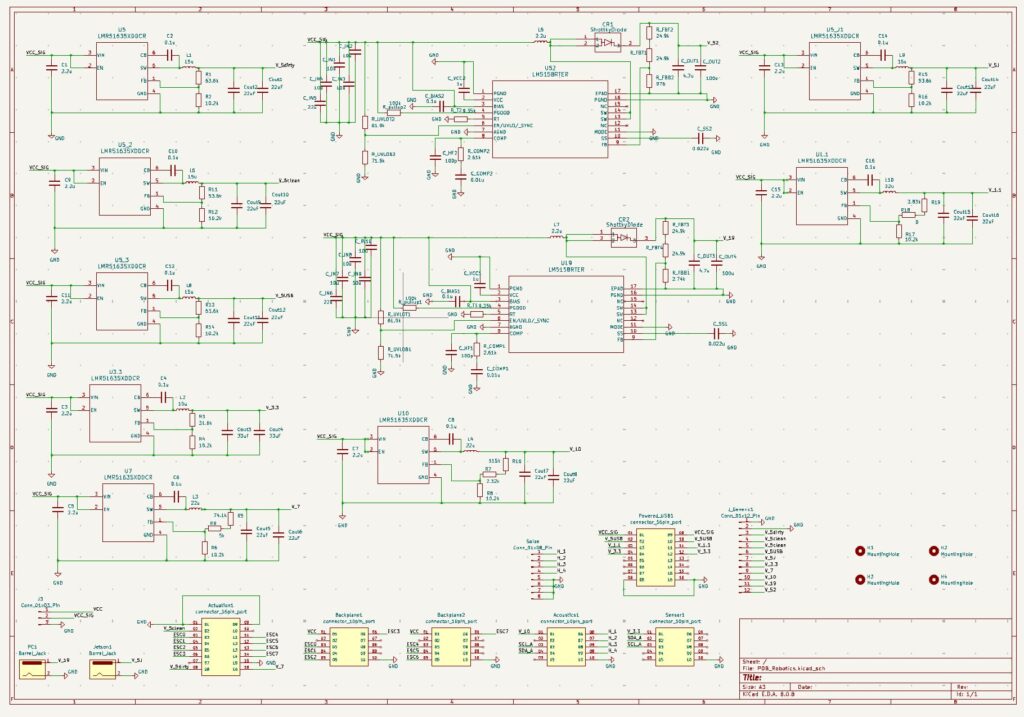
The PDB
At the heart of the redesign is a dedicated power distribution board. Rather than scattering regulators and protection across multiple boards, we now take battery input at one central point and generate all the voltages the system needs from there. The board distributes several rails, including raw battery voltage along with regulated 7 V, 5 V, and 3.3 V lines, with flexibility to add others if future subsystems require them. We’re treating this board as the foundation of the entire electrical system, so we’re building in protection and observability everywhere: fuses on each rail, power LEDs for quick visual checks, and plenty of test points so we can probe voltages without digging through wiring. The idea is that if something goes wrong, it should be obvious where the problem is.
Daughter Boards
From there, we’re moving to a backplane-style architecture. Smaller daughterboards plug directly into the PDB. Each daughterboard handles a specific function—sensing actuation, acoustics, or ESC control—and can be removed or replaced independently. This approach keeps the system organized and makes upgrades much easier. If we redesign the sensor board or add a new subsystem, we don’t have to touch the rest of the stack. It also helps isolate noisy components from sensitive ones, which should improve overall signal integrity.
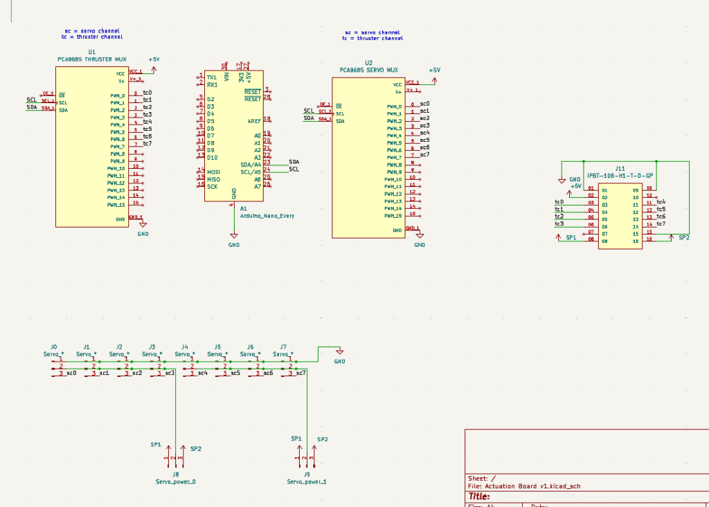
Actuation Board Schematic
On the actuation side, we’re consolidating all motor and servo control onto a dedicated board. This board interfaces between the main computer and the motor controllers, managing the logic needed to translate high-level commands into individual motor signals. It also distributes power locally for servos and smaller motors, which reduces the number of long power runs throughout the robot. The goal is to keep the connection to the main computer as simple as possible—ideally just one clean communication link—while everything else happens locally on the actuation board.
The sensor board is focused on environmental sensing and low-noise electronics. It handles things like temperature, humidity, and pressure sensors, along with any required level shifting or conditioning. Keeping these components on their own board protects them from electrical noise generated by motors and high-current systems. It also makes development easier, since we can iterate on sensors without worrying about the rest of the robot’s electronics.
One of the biggest improvements is how we’re handling the thrusters and their controllers. Instead of wiring each controller individually, we’re designing plug-and-play backplanes that hold multiple units at once. Each controller sits on a small adapter board that plugs into the backplane through a standardized connector carrying both power and signals. If one fails, we can simply unplug it and drop in a replacement without touching the rest of the system. This not only makes maintenance faster but also keeps the wiring neat and repeatable. We’re spending a lot of time choosing connectors that can handle both high current and lots of signal lines while remaining mechanically robust and easy to use.
Throughout the design process, we’ve also been thinking carefully about manufacturability. Wherever possible, we’re selecting parts that can be sourced and assembled through PCB assembly services so we can have boards delivered fully populated. That means less hand soldering, fewer assembly mistakes, and faster iteration. Instead of spending days building boards ourselves, we can focus more time on testing and improving the system.
Overall, this redesign is less about adding flashy new features and more about building a solid foundation. We want a system that’s easy to understand, easy to debug, and resilient to the kind of abuse that inevitably happens during testing and competition. By moving to a modular PCB stack with dedicated power distribution, backplanes, and swappable daughterboards, we’re turning what used to be a tangled mess of wires into something that feels like a real, engineered system. It’s been a lot of work, but we’re excited about where it’s heading—and even more excited for the day when fixing a problem means swapping a board instead of staying up all night with a soldering iron.
Excited for the future of Duke Robotics’ Electrical Stack!