We are proud to present Crush, our little guy for RoboSub 2026.
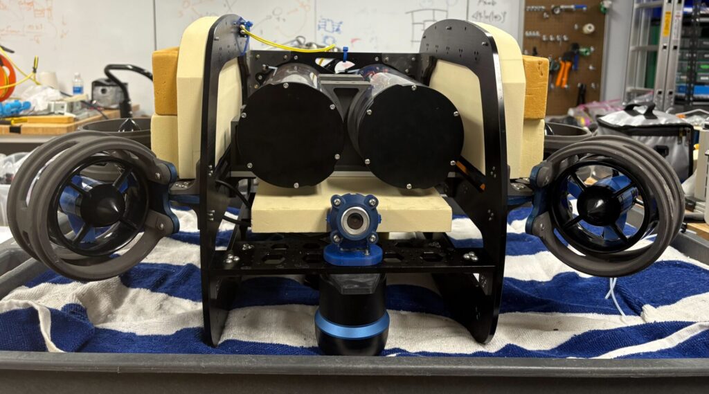
Crush is our newest autonomous underwater vehicle, designed for efficiency, modularity, and performance. It features a hydrodynamic frame shaped through fluid simulations to reduce drag and prevent unwanted pitch. A dual capsule system separates power and signal components, reducing electromagnetic interference and making both systems easier to access and service.
Crush is equipped with eight thrusters for precise movement and standardized mounting patterns for fast configuration and repair. The rail-based frame supports future hardware expansion, and removable capsules simplify maintenance. Equipped with sonar and a high-precision marker dropper, Crush can dynamically interact with its environment. At half the weight of Oogway, Crush is lighter and easier to handle—but just as capable.
Under the hood, Crush runs fully isolated power grids and a robot-independent electrical architecture. It supports underwater communication via acoustic modems and high-accuracy orientation sensing using a fiber-optic gyroscope and an IMU. On the software side, Crush runs on ROS 2 with a unified, robot-agnostic codebase, modular task planning, and a streamlined computer vision pipeline that cuts code complexity by two-thirds.
Come check out our Report!
Computer Science
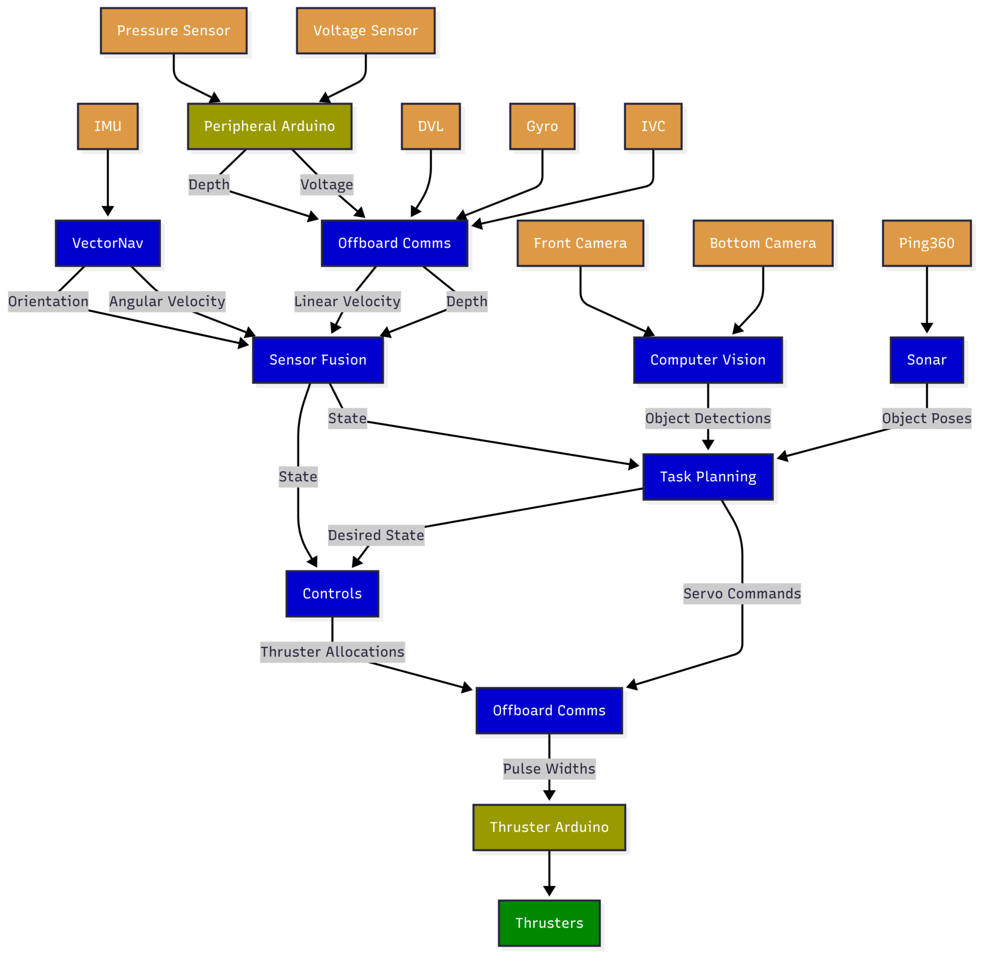
Robot Controls, GUI, Computer Vision (CV), Sonar, and Task Planning are crucial for autonomous robotics. Robot Controls manage movement and actions, while the GUI allows users to interact and monitor the robot. CV enables the robot to perceive and navigate its environment. Sonar sensors help with distance measurement and mapping, especially in low-visibility conditions. Task Planning determines the optimal sequence of actions for achieving goals. Together, these systems enable robots to perform complex tasks autonomously in dynamic environments.
Controls
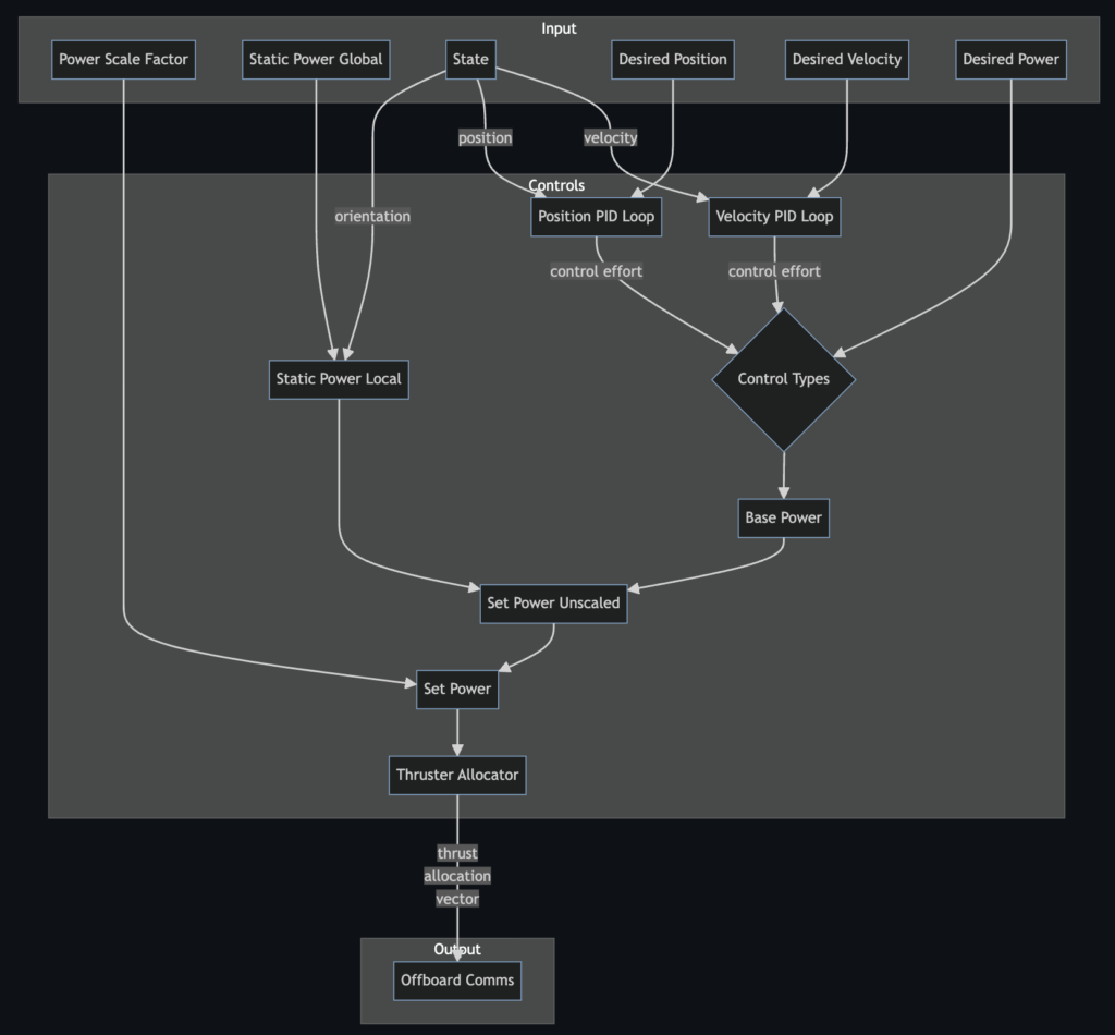
Our control system ensures precise and stable robot movement through a blend of feedforward and feedback control mechanisms. Feedforward control maximizes stability by counteracting persistent forces like buoyancy, while feedback control, implemented via Proportional-Integral-Derivative (PID) loops, ensures smooth navigation towards the target.
Further enhancing performance, the thrust allocator solves a quadratic programming problem using advanced numerical optimization techniques to determine the necessary force for each thruster, enabling the robot to follow the desired trajectory while minimizing energy usage. These forces are then transformed into pulse widths via a nonlinear mapping, and pulse width modulation is employed to spin the thrusters. This sophisticated approach guarantees precise maneuverability across diverse environments and conditions.
GUI
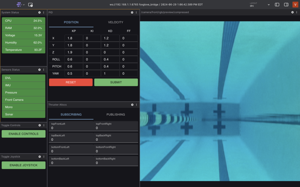
Built on top of Foxglove Studio using the React Material UI library, the Duke Robotics GUI features a modular and modern design and allows us to easily monitor and control our AUV during pool tests. We can receive real-time updates on the status of our onboard computer, sensors, thrusters, and battery. We can observe the performance of the control system and tune PID constants on-the-fly. We can use a joystick to control the robot directly. Individual panels are organized into layouts and easily deployed using a custom CLI. The GUI also supports replaying recorded ROS bag files for offline debugging and analysis.
CV
Detection
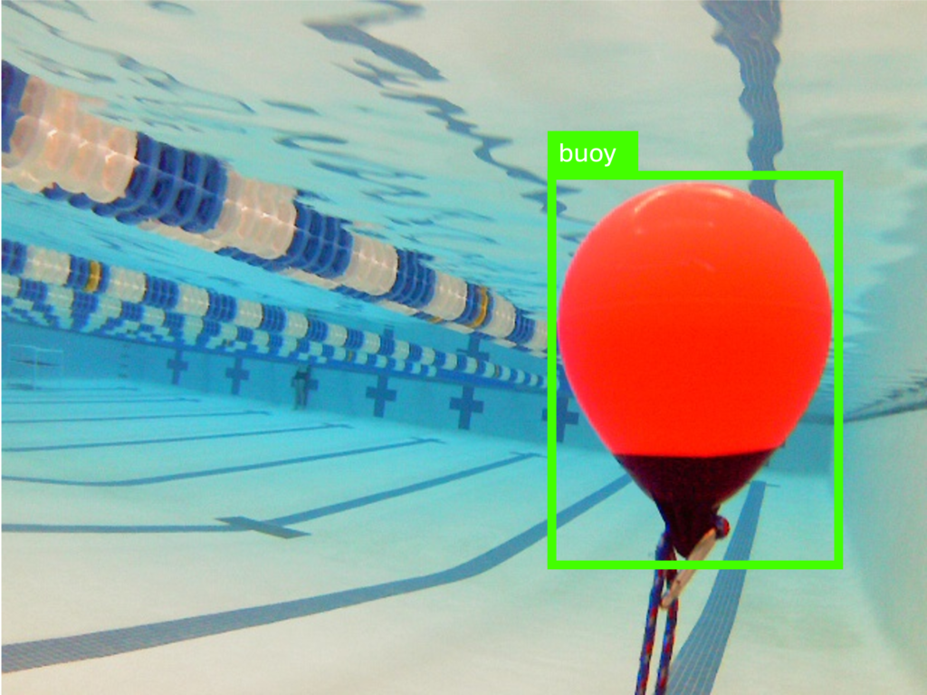
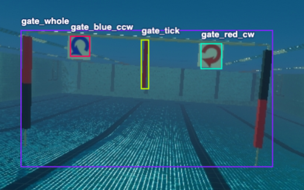
The computer vision (CV) system uses stereo and mono-vision inputs from both our DepthAI and USB cameras to locate items underwater to complete our underwater tasks. For simpler prediction tasks, we employ HSV filtering and contour matching to identify the slalom, path markers, and bin. For more intricate images encountered in the gate, torpedo, and octagon tasks, we utilize YOLO object detection models. Our enhanced CV pipeline seamlessly integrates these methodologies, dynamically adjusting to optimize detection speed and accuracy for various tasks.
Simulation
Our CV Simulation, built using Unity Perception, allows rapid generation of large-scale, labeled synthetic datasets for model training. Environment randomizations, such as rotations and lighting variations, contribute to a robust model that generalizes to a variety of diverse pool conditions. We also incorporated a realistic 3D model of the Woollett Aquatics Center to closely match the competition environment.
Sonar
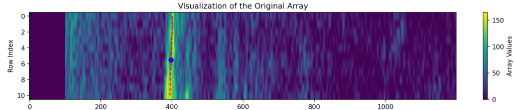
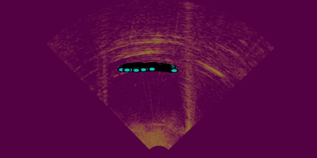
Our sonar system has been upgraded to enhance its reliability and provide alternate task completion methods. The upgraded sonar now effectively avoids false positives caused by acoustic reflections and can detect when the target object is missing.
Low-intensity values are filtered out, and the DBSCAN algorithm is used to identify clusters in the image. The clusters are used to identify the distance to the objects as well as their surface normal angles. The sonar can also perform long-range scans to get an overview of the AUV’s environment, filtering objects based on area and circularity and removing similar-sized neighboring clusters.
Task Planning
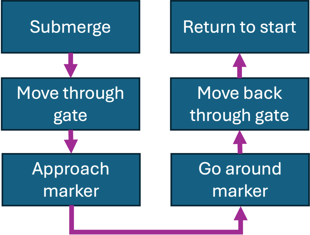
The task planning system serves as the robot’s top decision-maker, orchestrating its actions and responses to varying scenarios encountered during competition. It interfaces with all other systems, leveraging data from the robot’s perception capabilities and its current state to strategize and execute tasks efficiently by moving the robot or manipulating objects. Built upon a framework of coroutines, the system exhibits agility and responsiveness, swiftly adjusting to environmental changes and dynamically selecting the most optimal course of action at any given moment. The framework also facilitates streamlined development, allowing developers to assemble small building blocks into intricate tasks with ease. An automated system continuously publishes updates at every step, offering real-time insights into the system’s behavior and performance.
Electrical
The Electrical Stack consists of two isolated capsules—power and signal—designed to reduce interference and improve reliability. Internal mounts secure components like sensors, ESCs, and control boards. A dual microcontroller architecture separates critical thruster controls with real-time sensor readings. Integrated actuators and sensors, including a fiber optic gyroscope and acoustic modem, enable precise control and communication.
Full Electrical System
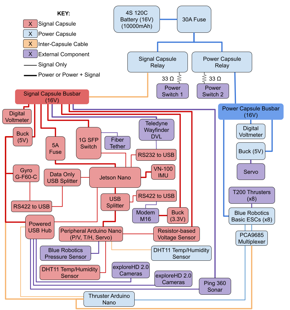
The electrical stack is the heart of the robot. Its primary responsibility is twofold: powering all components and ensuring all data gets to the right places. This includes everything from communicating with all sensors, powering the robot computer, and even ensuring a network connection to the GUIs running on our landside computers.
Last year, we built our new robot, Crush, drawing heavily from Oogway’s framework while optimizing and innovating. This year, we repaired unreliable connections and built on the knowledge from previous competitions and pool tests. We also enhanced the power distribution system within the electrical stack, further separating existing components to ensure they receive consistent current delivery.
Sensors
Crush relies on many sensors to track both external and internal conditions.
Our primary sensors determine the robot’s state, that being its 6 degrees of freedom: x, y, z, roll, pitch, and yaw. Our IMU, DVL, gyroscope, and pressure sensor are fused in software to provide an accurate state. The IMU, DVL, and gyroscope all have their own direct UART serial connection to the PC, whereas the pressure sensor is read through an Arduino and sent to the main ROS node over USB.
Crush has an onboard sonar, which is connected through USB to the computer.
We also have an internal voltage sensor to monitor the battery and dynamically adjust thruster speed, a temperature sensor to monitor capsule heat, and a humidity sensor to detect water ingress. We also read data from these three internal sensors with an Arduino.
Cameras
Crush is equipped with two USB cameras mounted at the front of the robot, which we use for visual monitoring during operation. These camera feeds assist our team during testing and troubleshooting.
One of these cameras has been mounted to face downwards at the path markers and the pool floor. This enables Crush to track path markers as well as any competition objects near the floor.
Thrusters + Servos
Crush features eight thrusters, and the electrical team provides the hardware abstraction layer used by the controls system.
Each thruster requires a precise PWM signal from the PC. To manage this, we communicate with an Arduino Nano over serial, which interfaces with an I2C multiplexer to control all eight thrusters. The I2C multiplexer is configured to ensure proper PWM outputs are produced based on its internal clock frequency.
In addition to the thrusters, Crush is equipped with a new servo to control a marker dropper. When ROS sends the appropriate commands, we can now deploy team markers from both robots as needed.
Inter-Vehicle Communication
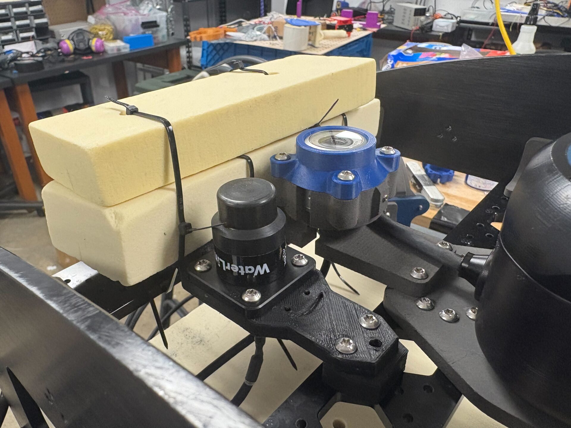
Crush has also been fitted with a WaterLinked M16 acoustic modem to enable underwater communication with other robots. The modem’s omnidirectional capabilities allow Oogway to send and receive data from anywhere in the pool without needing to reorient, making it ideal for collaborative, multi-robot tasks.
To support this integration, we developed a custom interface that links the modem to the onboard computer. This interface manages serial communication, publishing incoming messages to a ROS topic and sending outgoing data through a ROS service, as well as ensuring seamless operation within our modular, robot-agnostic system.
Mechanical
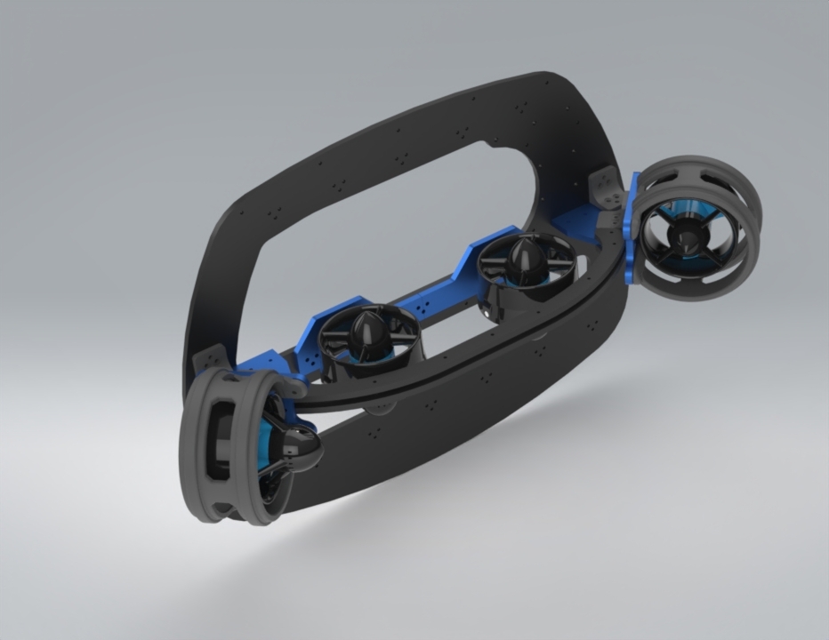
The Mechanical Frame is a streamlined, hydrodynamic structure designed to minimize drag and improve stability. A dual-capsule layout supports modularity and separates critical systems. Standardized mounts, mirrored walls, and repeatable patterns make components interchangeable and easy to service. Bottom rails allow for future expansion with task-specific hardware. Together with the custom CFD-Optimized Case and Custom Buoyancy system, this architecture enables future upgrades and major hydrodynamics enhancements.
Mechanical Frame
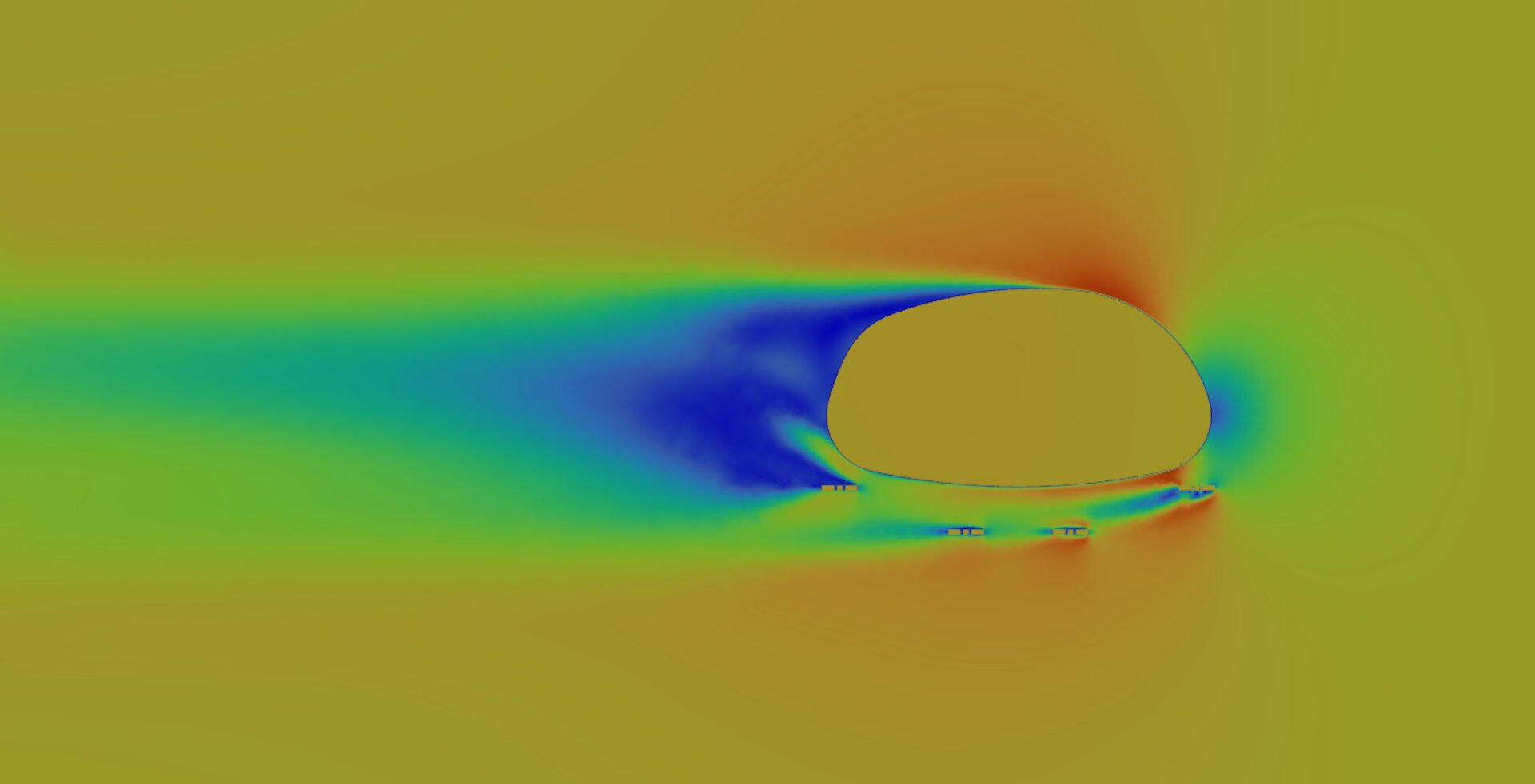
Crush’s frame was designed around a dual-capsule concept that isolates power and signal electronics to reduce interference and simplify system layout. This decision directly influenced the overall form factor, resulting in a compact, streamlined aluminum chassis. Fluid simulations were conducted to refine the frame geometry, ensuring low drag and resistance to pitch instability during movement.
Standardized Mounting Pattern
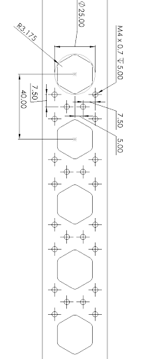
To improve serviceability and reduce manufacturing complexity, Crush adopts a consistent mechanical architecture using standardized brackets, repeatable mounting patterns, and a shared rail system. This includes mirrored frame walls and uniform mount geometries, allowing components to be easily swapped or repositioned. These standardized mounts are used for critical hardware like thrusters, sensor brackets, and capsule frames. The integrated rails provide flexible attachment points for internal and external components, supporting future expansion such as additional sensors or task-specific tools. The mirrored layout also enables symmetrical weight distribution, simplifying buoyancy tuning and reducing the need for manual balance adjustments.
Inter-Capsule Mounts
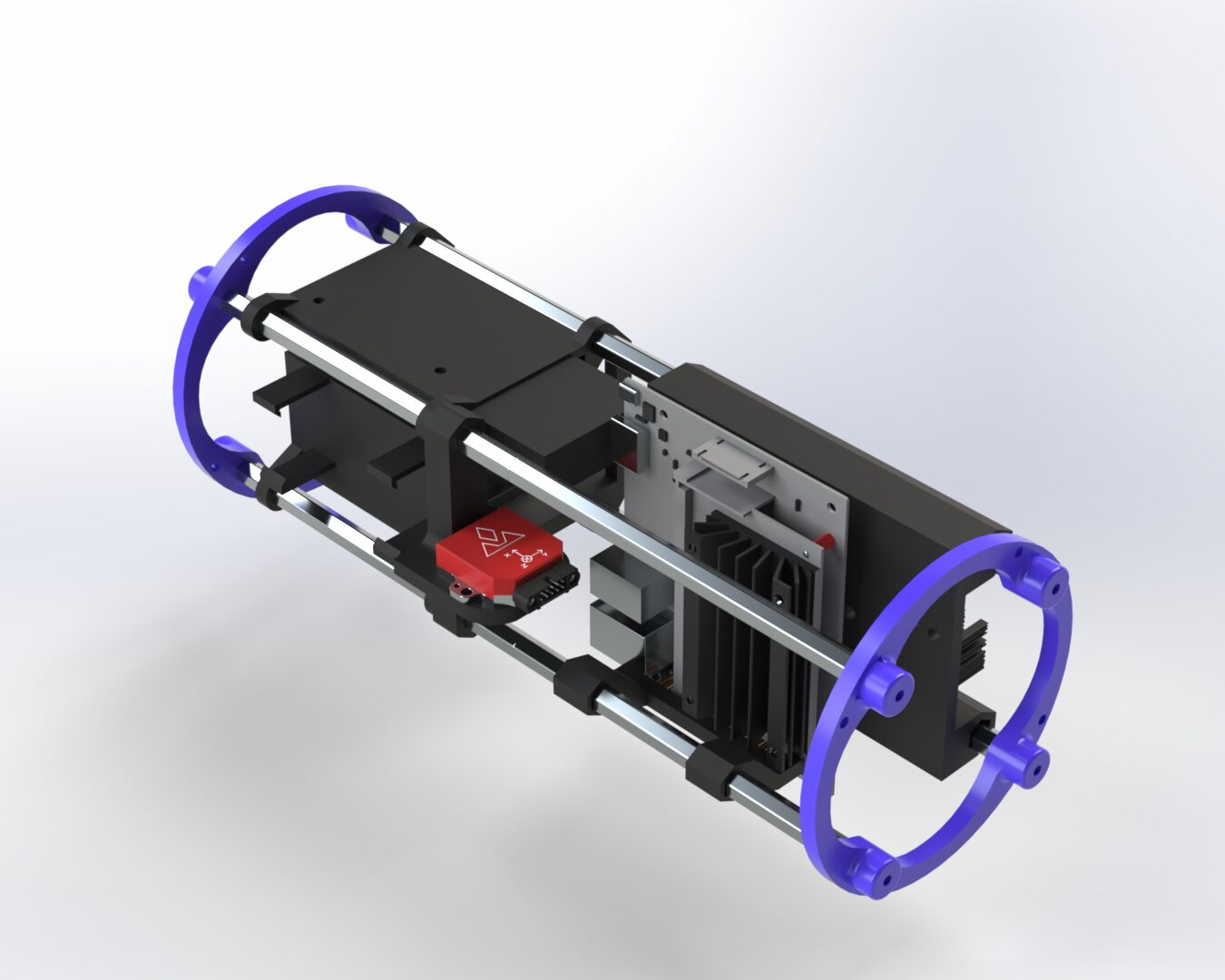
Crush’s electrical system is split between two capsules—signal and power—both built on a shared rail-based chassis that allows components to slide into place for organized wiring and efficient use of space. The power capsule houses high-current components like ESCs and the battery, while the signal capsule contains sensors and computing hardware. Components are densely packed using modular sleds, with some mounts supporting multiple devices. Layout revisions improved space use and simplified wiring, and the sliding rail system allows damaged sleds to be easily replaced.
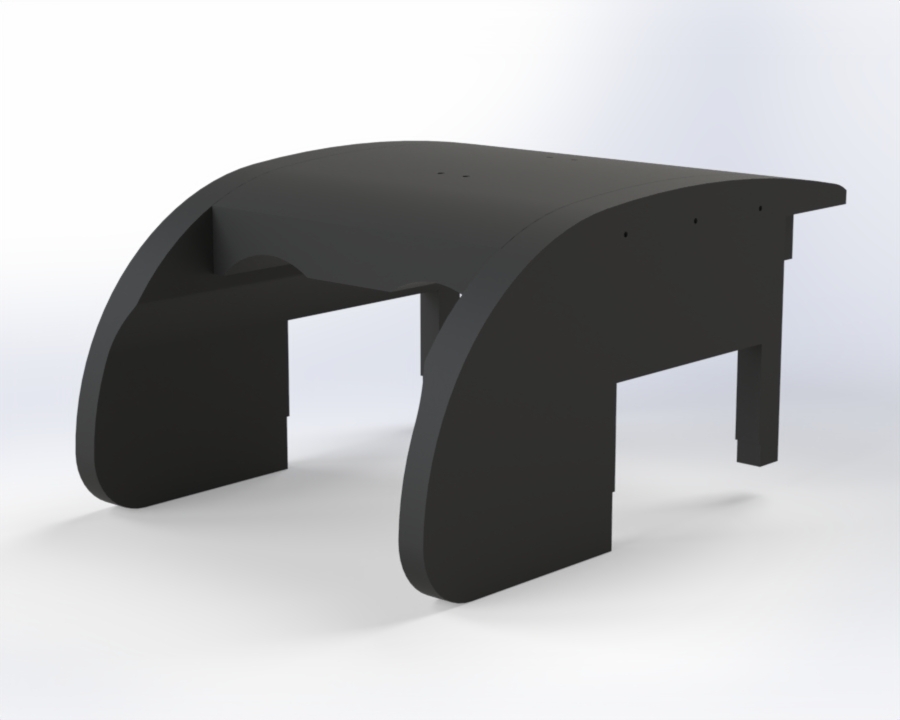
CFD-Optimized Case
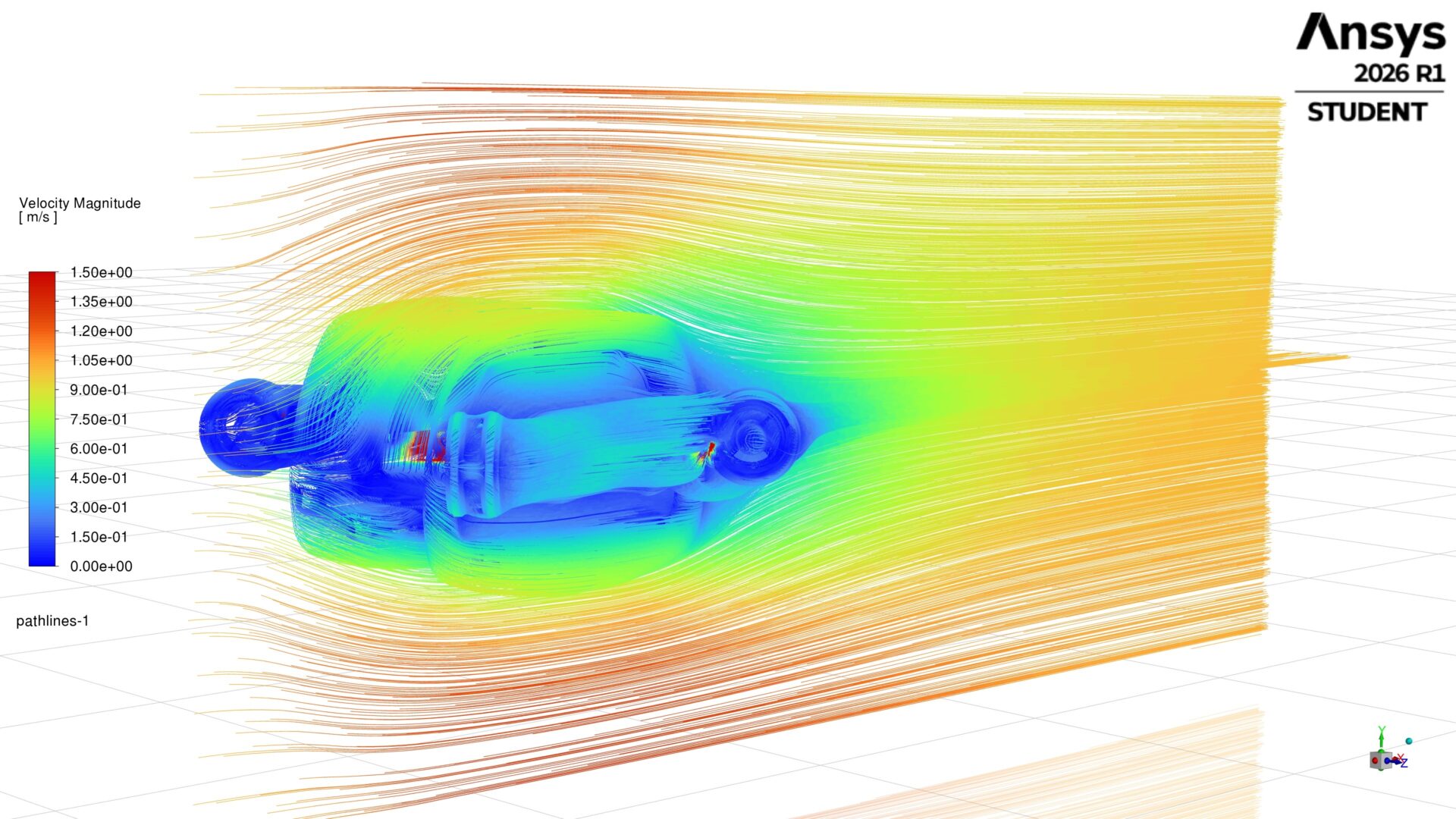
Crush’s frame and case were designed to fully enclose the dual-capsule design and reduce drag. The case follows the contours of the frame and is made from SLS 3D printed nylon to provide optimal strength while keeping the weight down.
Fluid simulations in Ansys Fluent were used to simulate the water flow around the robot, and it was determined that the case reduced drag by 29% as compared to not having a case.
Custom Milled Buoyancy
Crush’s new buoyancy blocks were CNC milled to fit exactly inside the case and around the capsules. The Center of Buoyancy was fine-tuned to be directly under the center of mass, which is optimal for staying level when underwater.
The blocks were all designed to be easily removed in under 1 minute, so they do not impede on the capsules when work needs to be done. Finally, the buoyancy blocks were painted black to boost the aesthetics of the robot!