You are “The Turtle Package” ;-)
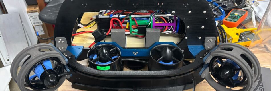
It’s been a busy few weeks in the lab as we juggle midterms and dysfunctional robots, but here we still are as we dive deep into the R&D for our newest project. From custom sonar mounts to CNC aluminum hulls, here is the latest from the mechanical team. Crush We have created a new sonar …