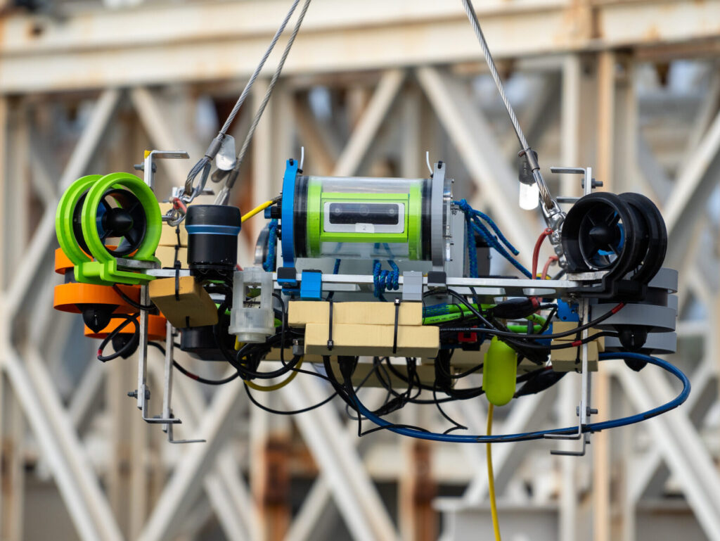
The electrical stack is the heart of the robot. Its primary responsibility is twofold — power all components, and ensure all data gets to the right places. This includes everything from communicating with all sensors, powering the robot computer, and even ensuring a network connection to the GUIs running on our landside computers.
This year, we rebuilt our electrical stack for two reasons. For one, we recognized a need for future expansion and overall optimization of component layout. And second, our capsule flooded.
Sensors
Oogway relies on many sensors to track both external and internal conditions.
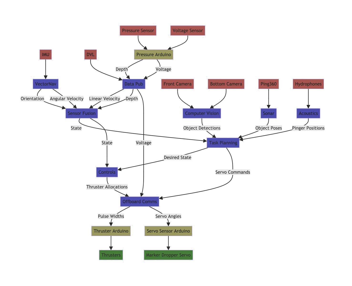
Our primary sensors determine the robot’s state, that being it’s 6 degrees of freedom: x, y, z, roll, pitch, yaw. Our IMU, DVL, and pressure sensor are fused in software to provide an accurate state. The IMU and DVL both have their own direct UART serial connection to the PC whereas the pressure sensor is read through an Arduino and sent to the main ROS node over USB.
Oogway has two sonars onboard, both of which are connected to the computer’s USB.
We also have an internal voltage sensor to monitor the batter and adjust thruster efforts, a temperature sensor to monitor capsule heat, and a humidity sensor to detect water ingress. Each of these three internal sensors are read with an Arduino as well.
Cameras
Oogway has four cameras that we use for CV and monitoring. Two cameras are simple USB cameras rated for underwater and two are sophisticate stereoscopic cameras with internal processing. These cameras represent a significant demand for both our power and data systems.
We also utilize downward facing cameras to track path markers on the pool floor.
Thrusters + Marker Dropper
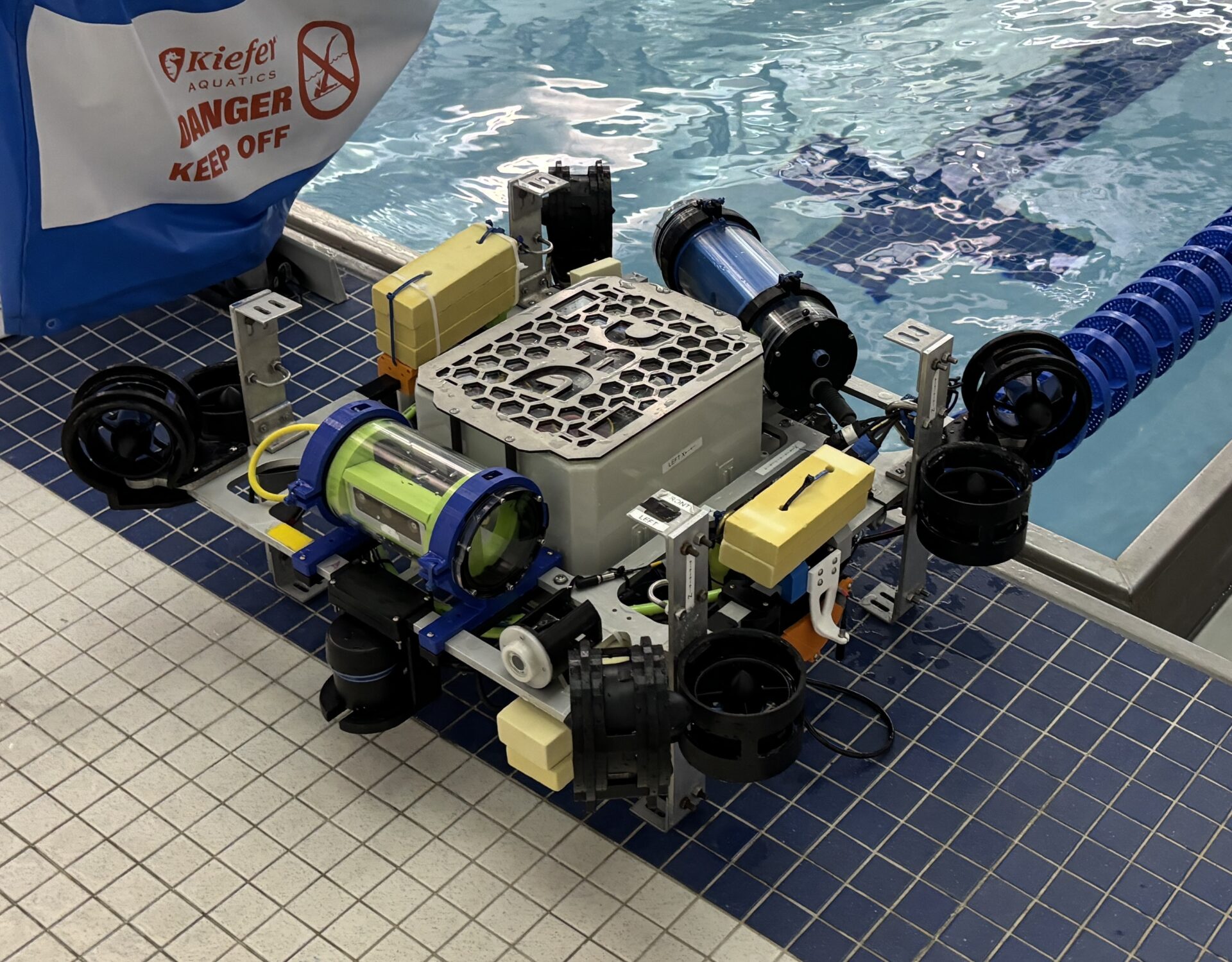
Oogway has 8 thrusters and it is electrical’s reponsibility for providing the layer of hardware abstraction used by controls. There are multiple challenges associated with the thrusters.
For one, the thrusters are located outside the capsule. With three 14AWG wires each, the thrusters introduce significant capsule penetration. Additionally, the ESCs mounted inside the capsule are physically large and come with significant wire mass when all power, data, and output wires are connected.
Additionally, the thrusters each require a precise PWM signal to be generated from our PC. Therefore, we run serial communication to an Arduino Nano Every that use an I2C multiplexer to initialize and control all thrusters. We have made corrective offsets to hardware defects that we measured on some ESCs.
Our marker dropper contains a servo that is connected to one of our Arduinos. Upon receiving the proper command over USB from ROS, we can individually drop both rounds from our dropper.
Networking
Oogway has its own onboard 4x RJ45 + 1x SFP unmanaged switch, used for a variety of purposes.
Our two DepthAi cameras are network-controlled. Therefore, we have fast data streams through our 1G switch. Further, both cameras are POE, meaning they get both power and data from their ethernet connections. Previously we had a POE switch, but we have pivoted to a more power efficient non-POE switch. We have created our own POE injectors downstream from the switch that comply with IEEE 802.3a Class A.
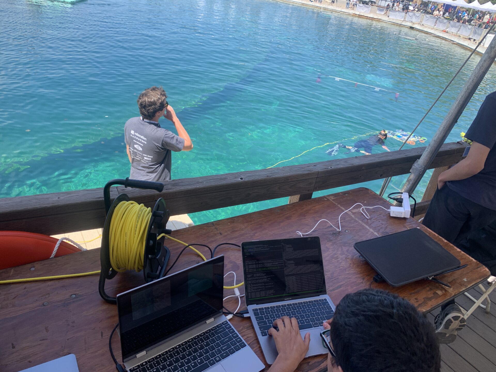
The switch also serves to establish landside connections. This is especially important during underwater operations, as water serves as a barrier to WiFi connectivity. We have a copper connection through an Cat6 tether and a new fiber connection, providing a more water-resistant interface.
Finally, the local network also serves in our Dockerized ROS enviornment. By attaching the Docker process to Oogway’s IP on the network, we can SSH into the container from multiple computers.
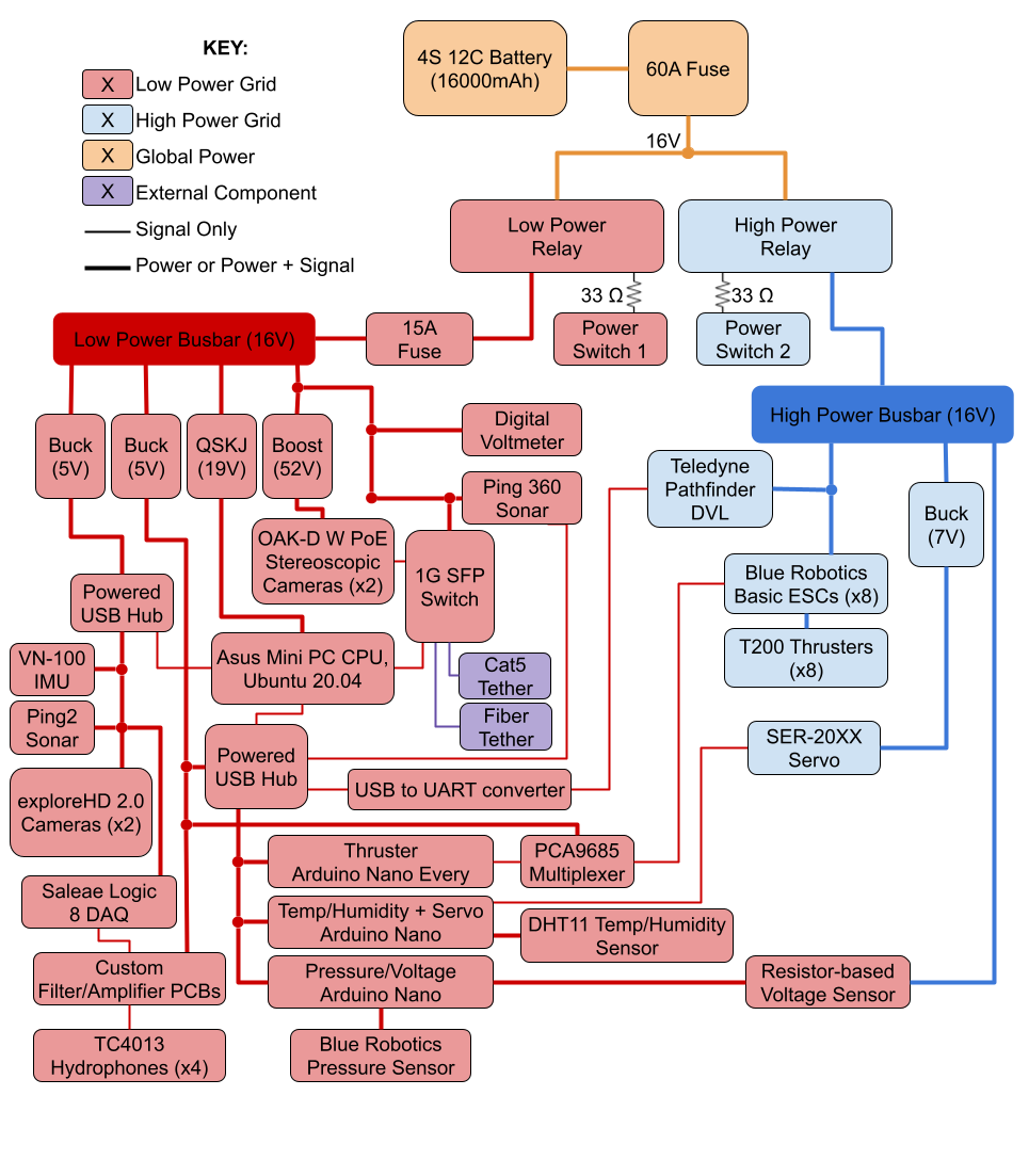
Power
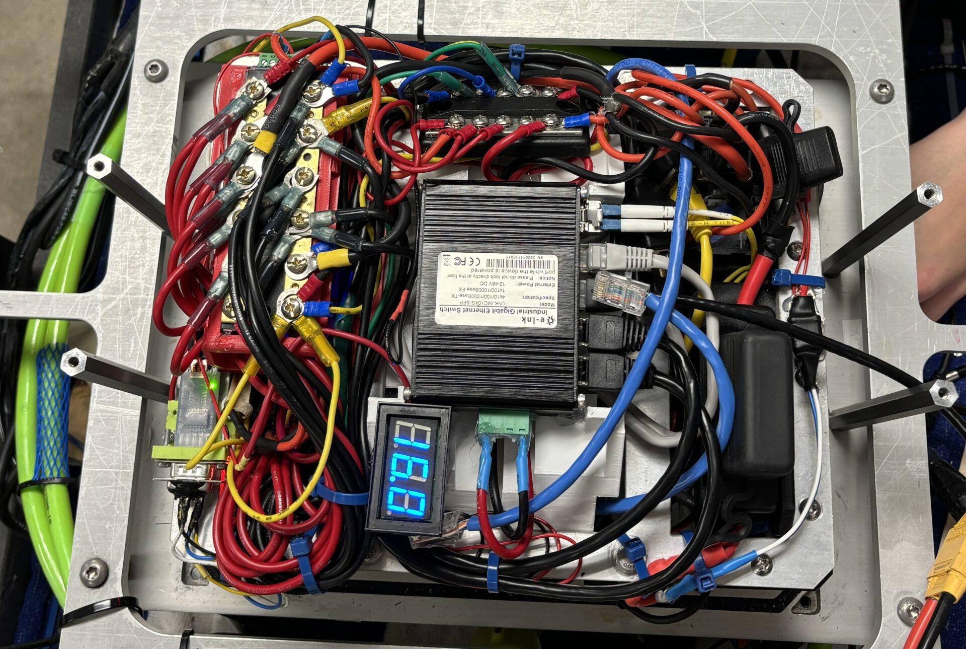
Oogway has two power grids, supporting the two major component types: one for sensitive low-power and land-safe operations (ex. CPU, cameras), and the other for power, underwater-operation-only components (ex. thrusters, DVL). Each grid has its own fuses and relay, providing added safety and control over our electrical systems.
We’ve also constructed a battery simulator for use during lab testing, meaning we don’t have to degrade or cycle our batteries during extended testing.
Within the stack, we have many DC-DC converters to provide necessary voltage levels for components such as the PC, powered USB hubs, servos, and the POE injectors. In total, Oogway has voltage rails at the following voltages: 52, 19, 14.8, 7, 5.
Acoustics
The acoustics subsystem aims to locate an acoustic pinger in the water. While still in development, it involves both custom hardware and software.
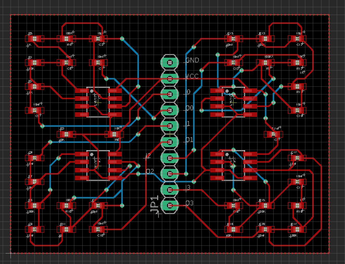
Oogway has 4 hydrophones, each of which has its own custom filters and amplifiers tuned for the pinger signature. When the analog data is read in with a DAQ, the pings are visible in the raw data, even when the pinger is located far away.
Software-wise, we apply both software filters and a statistical threshold to find the time of the pings. From there, we set up a time of arrival problem, that we solve with gradient descent. All of this software is written in Rust as these computations are substantial. Our unique approach utilizes the accurate state of the robot to accumulate many rough guesses from various positions.
Future work aims to develop FPGA processing and improve our time of arrival algorithm. Perhaps, we will consider switching to the MUSIC algorithm in the future.